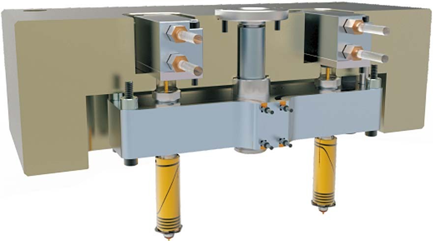
Plastic injection molding holds a significant place in modern manufacturing. The crucial aspect in the design of these molds is ensuring that the molten plastic reaches the mold cavity at the desired temperature and time. Therefore, runner design is critical. For the mold to operate efficiently, the correct identification of runner and product entry points is essential; otherwise, the mold cannot achieve the desired efficiency.
This article explores various types of runners, their features, advantages, and disadvantages to answer the question of how to select the appropriate runner channel and product entry point based on desired characteristics. For example, “if the product and runners are to separate automatically after the injection process, a pin gate should be used.”
INTRODUCTION
In plastic injection molds, the channels that allow the rapid and low-pressure loss filling of the mold cavity with molten plastic are called runners. Runners come in various shapes and sizes and are designed according to the product’s characteristics and production volume. Factors such as product shape, size, and surface quality are the main factors influencing runner design. These factors must be assessed at suitable levels, and the runner shape must be selected and designed accordingly.
Another crucial feature of runners in plastic molds is that product entries can be made in different shapes depending on conditions (product shape, size, surface quality, etc.). The main product entry types include edge gate, diaphragm gate, pin gate, tunnel gate, and fan gate.
2. RUNNER SYSTEMS
2.1 Definition
The channels that allow the molten material to reach the mold cavity are collectively called the RUNNER SYSTEM. Runner systems vary in shape depending on the shape and size of the cast part and its alloy. The molten material poured from the pot fills the mold cavity by passing through the vertical and horizontal channels that make up the runner system.
2.2 Functions
- Ensure the mold is completely and perfectly filled.
- Prevent turbulence and splashing in the flow of the molten material.
- Adjust the flow rate of the molten material.
- Balance the cooling and solidification.
- Prevent air and other gases from being entrained into the mold and absorbed by the liquid metal.
- Do not increase mold labor.
- Minimize molten material loss.
2.3 Components of the Runner System
Runner systems consist of three main parts:
- Sprue (Runner Cone)
- Distribution Channels
- Gate (Product Entry)
2.3.1 Sprue (Runner Cone)
The cross-section of the channel is circular to minimize pressure loss, and it has a conical angle of 2° to 5° for easy removal from the mold. The channel in the sprue bushing forms the sprue. The molten plastic material flows into the sprue bushing from the injection nozzle during the injection phase after the mold closes. This area of the mold wears quickly due to high pressures, so the sprue bushing should be made of hardened steel and mounted in the mold for easy replacement if it wears out.
The dimensions of the sprue depend on the size and wall thickness of the part to be produced. The sprue must be easily and safely removable from the mold.
2.3.2 Distribution Channel
Distribution channels connect the sprue and the gates. The most commonly used distribution channel shapes are circular, semi-circular, trapezoidal, and rectangular. The design and dimensions of distribution channels are critical aspects of mold design. They should be sized to minimize pressure loss and accelerate the flow of molten plastic, but not so large that the plastic solidifies within them.
2.3.3 Gate
Gates are the connection points where the molten plastic enters the mold cavity. The plastic flows from the sprue to the mold cavity through the gate. Gates must be precisely machined; otherwise, flash can occur in the molded part. Various gate types include pin gates and conventional gates.
2.4 Gate Types
Once the gate location is determined, the appropriate gate design and geometry are selected. The gate design varies depending on its use. For example, direct gating is used in single-cavity molds or large single-part molds, where the machine nozzle directly delivers plastic to the mold, eliminating the need for a runner system.
2.4.1 Edge Gate
The edge gate is the simplest gate design and is easy to machine, typically by taking one pass with a milling cutter. Despite its simplicity, its application is limited because it does not have good mold filling characteristics. The molten plastic may flow unevenly, creating defects in the part.
2.4.2 Fan Gate
The fan gate is a modified form of the edge gate, used to fill thin parts. The molten plastic spreads out as it enters, ensuring smooth mold filling. However, due to the large gate area, trimming the gate after molding can be problematic.
2.4.3 Diaphragm Gate
Used for cylindrical or hollow parts requiring concentricity and strength, the diaphragm gate ensures balanced mold filling with a recommended minimum land length of 0.5-1 mm.
2.4.4 Ring Gate
The ring gate is typically used for cylindrical parts where the internal diameter is more critical than the external diameter. The gate depth is usually determined through mold trials.
2.4.5 Spoke Gate
Used when the part is too large for a diaphragm or ring gate, the spoke gate allows a large volume of polymer to flow, making it suitable for thick, heavy parts requiring high shot weights.
2.4.6 Tunnel Gate
The tunnel gate enables automatic separation of the gate from the part after molding. However, due to its embedded design, adequate mold ventilation is essential to prevent gas burns in the part.
2.4.7 Pin Gate
Pin gates are used in three-plate molds, allowing automatic separation of the gate from the part. The gate size is reduced for clean separation, but this makes the gate prone to damage and wear, especially with filled plastics.
2.4.8 Tab Gate
The tab gate reduces jetting and ensures smooth filling of large decorative parts where aesthetics are important, such as toolboxes. However, trimming the tab can be costly, so the gate should be positioned to facilitate subsequent operations like painting.
CONCLUSION
This article provides a general overview of runner systems, emphasizing their importance in design and the conditions under which different types should be selected. The focus is on product entry types, as most issues stem from incorrect gate selection. Problems like sedimentation and incomplete molding are common. The article stresses selecting the appropriate runner based on product characteristics.
REFERENCES
- Turkish National Education Vocational Education Development Project, (megep) Plastic Injection Machines 1, ANKARA/2007
- Introduction to Plastics and Plastic Injection Technology, Pagev Publishing, ISTANBUL/2004
- ERIŞKİN Yakup / UZUN İbrahim, Volume Molding, M.E. B Publishing, ISTANBUL /1984

